


 Sign In
BIM Clash Detection: A Practical Guide to Catching Conflicts Before They Reach the Field
Key takeaways:
BIM clash detection should be run early and repeated as a loop to catch conflicts while they’re still a cheap model edit instead of a field change order that drags in multiple trades.
A clash report is only as trustworthy as the geometry behind it, so the model has to be validated against real site conditions to avoid false positives and missed conflicts.
Field-verified digital twins and point clouds anchor clash tests to as-built reality, letting every trade measure and resolve conflicts against the building as it actually stands.
A conflict that never appeared in the federated model shows up anyway on site: a duct crossing a beam, a pipe through a wall, two trades laying claim to the same few inches of space. Now the fix is a change order, a crew standing idle while an RFI works its way back, and an argument over whose budget absorbs it.
That collision was predictable weeks earlier. BIM clash detection catches these conflicts before they reach the field. It works best under two conditions: it has to run early, while the fix is a markup rather than demolition, and it has to run against geometry that truly reflects the condition of the site or existing building.
Miss either one and clash detection becomes a report nobody trusts. This guide walks through how to get both right.
What is BIM clash detection?
BIM clash detection is the process of finding where systems in a building information modeling (BIM) model conflict with one another, so teams can resolve them before they become problems in the field.
Each trade builds its own: the architect models the building, the mechanical engineer the ductwork, the plumber the piping, and so on. These are then combined into a single coordination model, called a federated model, where pipes, ductwork, conduits, and structural members can be checked against one another for interference. Coordination happens through a virtual design and construction (VDC) workflow, before construction begins, so conflicts are resolved on screen rather than in the field.
You can sort clashes into three types: hard, soft, and workflow clashes. Each clash type needs its own tolerance rule and its own owner, which are documented in a BIM execution plan (BEP), so treat them as distinct problems.
Hard clashes
A hard clash is the simplest to picture: two objects occupying the same physical space. A common example is a sprinkler main routed straight through a structural beam, where neither element can give way without a redesign. These are the most obvious conflicts because the overlap is literal.
Running the test early, while the fix is still a model edit:
Catches physical overlaps during design, before they become field rework.
Keeps installation sequences from stalling on a blocked route.
Reduces change orders tied to conflicts discovered on site.
Set the overlap tolerance close to zero; a small threshold of roughly 10–25 mm keeps minor modeling noise out of the report while still flagging any real intersection. Resolution usually falls to the MEP trades, since structural elements rarely move.
Resolved early, hard clashes are a model edit; resolved late, they are a site problem.
Soft clashes
A soft clash is a violation of a required clearance, access, or maintenance zone, sometimes called a clearance or buffer clash. Nothing physically overlaps, but the installed condition breaks a rule. Classic examples are an HVAC unit set too close to a service walkway, or a duct run that leaves too little working clearance in front of an electrical panel.
Clearance rules must be defined in the clash test for a soft clash to surface. If those buffers are never set, the software has nothing to measure against and will not flag the conflict.
Defining the clearances and testing against them:
Protects code-required clearances and safety zones.
Keeps equipment reachable for maintenance over its service life.
Avoids late redesign when an access rule is missed.
The tolerance here is the clearance itself: you enter the required buffer, such as the working space a code mandates in front of an electrical panel, and the test measures against it. Ownership sits with the discipline that owns the equipment and its clearances, since they know which buffers are non-negotiable.
A soft clash caught in coordination is far cheaper than a crew that cannot reach a panel after handover.
Workflow (4D) clashes
Some clashes come down to scheduling and sequencing rather than geometry. If excavation is still in progress when heavy equipment arrives, the two tasks might collide even though no model elements overlap. Another common version is two trades scheduled to install in the same ceiling zone during the same week.
Testing the sequence of work alongside the geometry:
Prevents trades from colliding in a shared work zone.
Keeps the construction sequence realistic and buildable.
Reduces downtime caused by scheduling conflicts.
There is no geometric tolerance to set here; the rule is that two tasks should not share the same zone in the same window, which a schedule-linked 4D model makes visible. Resolving workflow clashes usually falls to the scheduler or superintendent rather than a modeler, since the fix is a sequencing decision, not a model edit.
Caught in coordination, a workflow clash is resolved by adjusting the sequence before the work is scheduled, not by sending a crew home.
Why do clashes happen?
Clashes typically trace back to one of the following:
Poor model quality, with elements modeled loosely or inconsistently.
Low level of development, so geometry lacks the detail a real conflict needs.
Outdated files, where one discipline is working from a superseded version.
Missing clearance rules, so required access and service zones are never tested.
Late design changes that ripple through other trades unnoticed.
Disconnected 2D and 3D workflows, where drawings and models drift apart.
Most of these causes share a root: the model and the real building have diverged. Sometimes that’s a quality or versioning problem, caught by better standards and coordination. Other times the geometry itself is stale, because the model has fallen behind installed work on an active site, or never matched existing conditions on a renovation.
Why is early clash detection important?
Timing drives the entire value of BIM clash detection. A conflict caught at the preconstruction stage can be resolved with a model edit. The same conflict found after procurement, fabrication, or installation incurs material, labor, and schedule costs, and it usually drags in more than one trade.
A strong clash detection process isn’t just design hygiene. It prevents rework and disputes, and protects budget, schedule, and the working relationships between trades.
Early coordination pays off in:
Lower costs and less field rework
Better collaboration across disciplines working from one model
Fewer risks and less material waste
Faster approvals, with fewer RFIs and change orders
Clash detection does more than clean up a model when it runs early and against geometry that matches the site. It settles who installs what, and where, before the trades are standing in the same space arguing about it.
The BIM clash detection procedure in 6 steps
Clash detection is a repeatable loop. You aggregate models, test them, resolve conflicts, update, and run the checks again until the coordination model is clean. Every step in that loop depends on how accurate the incoming models are, so the quality of your inputs sets the ceiling on the quality of your results.
The sections below walk through what each step involves and the best practices that make sure the process is reliable.
1. Aggregate discipline models into a federated model
Before running clash detection, create a federated environment by combining all discipline-specific models into a single coordination one. Cloud-based tools like Autodesk Forma, whose Model Coordination runs automatic clash detection, or Navisworks Manage help aggregate the models on a set exchange schedule rather than ad hoc.
Before anything else, confirm every model shares the same origin point and coordinate system. If they are not aligned to a shared origin, the federated model will report conflicts that do not exist.
Run a short model-readiness check before coordination starts to confirm:
Agreed level of development per discipline
Aligned coordinates and a single shared origin
Consistent, predictable element and file naming
Confirmed current file versions from every trade
A defined model exchange schedule everyone follows
TIP: Keep file formats consistent across disciplines, such as IFC, RVT, and NWC, so models aggregate cleanly without conversion errors.
A clean, aligned federated model makes every clash test that follows more reliable, because the software is comparing real geometry instead of setup mistakes.
2. Validate the model against site conditions
Misaligned, incomplete, or outdated models create false clashes and hide real ones. Start with a quality pass on the aggregated model by running an audit in Solibri or Revit Model Checker to flag errors and rule violations. Then identify duplicate elements and check metadata for gaps or inconsistencies.
On renovations, additions, and active sites, the design model rarely matches what is physically there, so it’s important to create a baseline of real conditions to test against.
Scanning a space with reality capture technology produces a point cloud, a dense set of measured points describing the as-built geometry. Those points can also be used to create a navigable digital twin: a field-verified record of as-built conditions that trades can open and easily understand in a browser without a CAD or BIM license.
Reality capture data can be pulled into the coordination stack in one of two forms of as-built documentation:
A point cloud: E57 files import into ReCap Pro and Revit as a dense as-built reference to clash-test against.
A modeled deliverable: BIM Files provide RVT and IFC geometry at level of development (LOD) 200 across architecture, interior furniture, and MEP layers, with a Revit plugin that imports them without a separate conversion step.
Whichever form you use, ensure the capture method is suitable for the checks it has to support. Reality capture accuracy can range from a rough room layout to near-survey grade.
Matterport’s Pro3 camera uses LiDAR to capture accuracy within ±20 mm at 10 m in E57 and other generated files, enough to resolve most MEP and structural coordination clashes. Set clash tolerances no tighter than the capture accuracy, or use survey-grade scanning for any check that needs millimeter-level precision.
Overlay the as-built reference on the design model and look for where they diverge: elements that have moved, been installed differently, or were never modeled at all. Reconcile this before clash detection runs, so the test fires against geometry that matches the actual site rather than the drawing.
3. Run automated clash tests
Popular tools, such as Autodesk Forma or Navisworks Manage, can scan the federated model for conflicts automatically and generate a clash report. Set up tests one trade against another rather than running everything at once. Test MEP against structure, plumbing against fire protection, and so on, with a defined tolerance for each so the results are specific and readable.
Automation and AI-assisted filtering speed this process up, but keep in mind that they save time, not judgment. Automated clash checks are only as reliable as the data they have, so the tool cannot reliably flag conflicts finer than the accuracy of the reality capture. Feed it loose or outdated geometry and it may well return a report full of clashes that are not real.
Some best practices for this step in the procedure include:
Run tests incrementally as models mature, not just once near the deadline.
Keep tolerances consistent with the capture accuracy behind the model.
Load MatterPak point cloud and mesh files as a separate reference layer so you can toggle the scan on and off while reviewing flagged clashes.
A careful run produces a long report, but a meaningful one: every flagged conflict is worth reviewing.
4. Review, filter, and prioritize results
A single report can return hundreds of conflicts, which can easily stall coordination. However, many of these will be duplicates: clustered instances of one underlying issue, or overlaps that fall within tolerance. Work through the list to filter it down.
Group duplicates and clustered clashes together, apply your tolerances, and filter out false positives so coordination meetings focus only on conflicts worth resolving. Categorize what remains by type, then prioritize by severity, from critical to moderate to low.
Watch for three common pitfalls as you filter:
False positives from clearance rules or tolerances set too tight: loosen them to match reality.
Data inconsistencies from misaligned models, outdated plans, or mixed formats.
Trades disagreeing on resolution priority: settle any disputes based on severity and schedule impact.
Before you assign a flagged clash to a trade to resolve, pin down its real dimensions against the captured site. Open the site’s digital twin and use Measurement Mode to measure the actual distances, so the clash has specific dimensions attached for the trade to resolve it, not just a flag on a model.
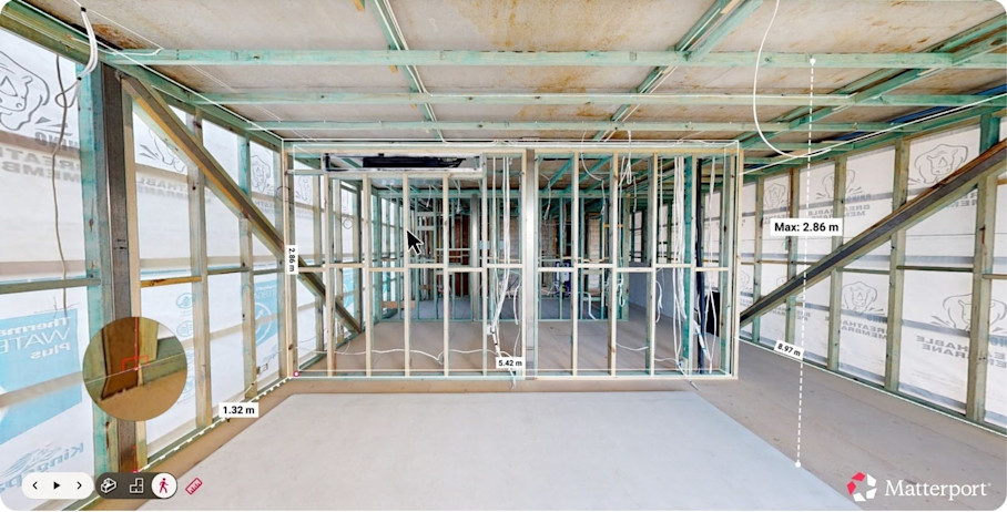
The result is a short, ranked list of real conflicts, each with the measurements and priority needed to resolve it.
5. Assign issues to responsible trades and track clash resolutions
An actionable clash report should define the following fields for each conflict:
Location in the building
Disciplines involved
Severity level
A screenshot or saved view
Responsible party
Due date
Most BIM coordination tools let you assign detected clashes to the right teams. Route each conflict to the discipline that owns the fix:
Structural engineers for framing, beams, and load-bearing conflicts
MEP teams for ductwork, piping, conduit, and equipment conflicts
Architects for wall, ceiling, and layout conflicts
A clash is easier to assign and resolve when it points to an exact spot rather than a model coordinate. Pin each conflict to the relevant location in the digital twin with Tags, to give the assigned trade full context and an easy route to the work they need to do. Teams that track issues in Procore can pin RFIs, Observations, and Coordination Issues to those same 3D locations, so the assignment lives where the rest of the project’s issues do.
When two trades disagree on a fix, a shared, browser-based digital twin gives them one verifiable reference to settle it against instead of competing interpretations of the drawings. Consistent, shared reports also help show coordination ROI to leadership. Track trends in RFIs, rework, and schedule slippage over time, so the value of early clash detection is clear to executives.
6. Re-run checks and update the models
As trades make adjustments, new clashes can appear, so clash detection is never a single pass. Trades update their models, coordinators re-run the tests, and the loop repeats until the coordination model is clean.
TIP: Close the loop with reality. Recapture the space again after installation so the federated model reflects as-built conditions alongside design intent, and compare on-site conditions directly against the updated BIM model.
Each pass through the loop gets shorter as model accuracy improves, because fewer real conflicts and fewer false positives survive into the next round.
Clash detection in practice: keeping models aligned with site conditions
Bologna digital engineering firm e-Making took on the restoration and seismic retrofit of the Remondini Palace, a building dating to 1600 that earthquakes had left badly damaged and highly irregular. On a structure like that, no drawing can be trusted to match what is physically standing, which makes it a clear test of coordinating against captured reality rather than against plans alone.
Their workflow ran like this:
Captured Matterport digital twins of the palace at each project milestone.
Shared the digital twin from each milestone with the architectural, structural, and MEP teams, so all three could analyze the same conditions and work concurrently.
Verified dimensions directly in the twin with Measurement Mode, reaching accuracy the firm reported as 50 times better than traditional methods on an irregular building.
Imported Matterport E57 point clouds into Autodesk Revit and ran clash detection across design phases, testing the architectural, structural, and MEP models against the as-built geometry.
Logged findings and kept the twins current with Tags through design and construction, so later decisions ran against updated conditions.
e-Making optimized its MEP distribution and eliminated inconsistencies between the architectural, structural, and MEP design before construction began.
With the project captured at each milestone, scans add up to a record of the same space over time. Where two captures exist, they can be aligned Side-by-Side (public beta), so a change between phases, a relocated pipe rack or a moved wall, stands out against where it used to be. Once a capture shows that site conditions have shifted, it signals that the clash tests need to run again against the newer geometry, before the design model drifts out of step with the building.
Whether you are testing a design against the as-built or one capture against the next, a Matterport record keeps clash detection anchored to the building as it really is.
Detect BIM clashes before they cost you
BIM clash detection is not only about preventing modeling errors. It is about protecting budget, schedule, and the working relationships on a project.
The projects that avoid field surprises:
Run clash detection early
Repeat it as a loop
Test against geometry that matches the site
Tie an as-designed model to as-built conditions, and most conflicts get resolved on screen long before they reach the field.
By combining high-accuracy 3D scans with a field-verified Matterport digital twin, teams across architecture, engineering, and construction workflows can catch design conflicts earlier, minimize rework, and keep projects on track.
Get in touch with our team